Project Description
K1 to RJ-45 Adapter
(FTDI USB cable)
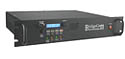
AnyTone AT-779UV
Radioddity DB-20-G
By: MichaelLAX W7ML / WRBU527
|
Background
For years to program my non-CHIRP radios, I used
Windows XP in Parallels on my Intel Mac Mini.
Historically I purchased the EZLink USB to K-1 cable
to program my original Baofeng UV-5R. It has a FTDI
chip and a transparent USB case has two LED
indicators to give data traffic information. This
cable works well with my Baofeng UV-5R, UV-5Rx3,
UV13PRO, TYT-88UV and Pofung BF-T11.
Both my Anytone AT-779UV and Radioddity DB20-G
came with its own USB to RJ-45 cables with,
according to Radioddity, a Prolific chip.
Although I continue to use that arrangement, I have
upgraded to a 2020 Apple Silicon M1 Mac Mini. The
use of Parallels on this Mac does not support XP, so
I upgraded to Windows 11, but the ARM architecture,
because there is no underlying Intel chip on the
Mac.
This has caused “upgrade” issues for my programming
cables.
Parts and Tools
List
The components were purchased from Amazon. You can
use alternate sourcing for the parts, but the
color-coding might be different.
RJ45 Cat 6 Ethernet
Patch Cable
Stereo 3.5mm Jack
Connector Audio Cable
Stereo 2.5mm Jack
Connector Audio Cable
Electrical tape
Soldering pencil or gun (optional)
Multimeter (optional)
__________
NOTE: If your color coding scheme is different, use
a Multimeter to determine the needed wires as
follows:
a) On the RJ-45, determine which wires go to pins 1,
3 and 8 respectively.
b) On a 3.5mm audio plug to bare wires, determine
which bare wire goes to the collar furthest away
from the center pin (Rx). Then plug the 3.5mm audio
plug into the 3.5mm audio jack to bare wires and use
your multimeter to determine which bare wire on the
jack matches the Rx wire on the plug.
c) On a
2.5mm audio plug to bare wires, determine
which wire goes to the collar furthest away from the
center pin (Gnd). Then plug the 2.5mm audio plug
into the 2.5mm audio jack to bare wires and use your
multimeter to determine which bare wire on the jack
matches the Gnd wire on the plug.
d) On a 2.5mm audio plug to bare wires, determine
which wire goes to the collar in the middle of the
plug (Tx). Then plug the 2.5mm audio plug into the
2.5mm audio jack to bare wires and use your
multimeter to determine which bare wire on the jack
matches the Tx wire on the plug.
_________
Instructions to
build adapter:
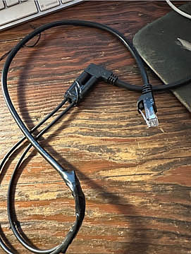
1) Take the Cat 6 Ethernet Patch cable and cut the
wire about 12 inches from the RJ-45 connector.
2) At the cut end, remove about 1 inch of the outer
insulation of the wire, revealing all of the 8
color-coded internal wires.
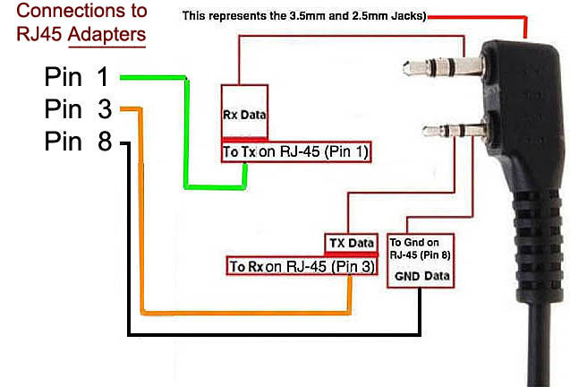
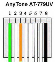
3) We want to focus on 3 of these 8 wires for the
RJ-45; the ones connected to Pins 1, 3 and 8.
The color coding on the Amazon purchased Cat 6 cable
is: 1=White/Green; 3=White/Orange; and 8=Black.
4) On the 3.5mm Jack, we want the Black wire
5) On the 2.5mm Jack, we want the Black and White
wires.
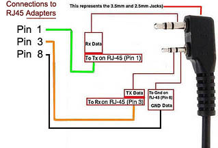
6) Connect the RJ-45 White/Orange wire (RX) to 3.5mm
Jack Black wire (Rx Data)
7) Connect the RJ-45 Black wire (Gnd) to 2.5mm Jack
Black wire (Gnd Data); and
8) Connect the RJ-45 White/Green wire (TX) to 2.5mm
Jack White wire (TX Data)
9) Use your Solder gun/pencil to apply some solder
for better connectivity and strength.
10) Test the adapter and when you are sure the
adapter and USB cable are properly functioning, cut
off the remaining unused wires on the RJ-45 cable
and the 3.5mm and 2.5mm Jack cables.
11) Wrap each of the 3 connected wires apart from
each other and use electrical tape to insulate them
and fasten the ends of the two cables together.
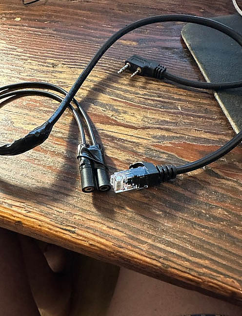
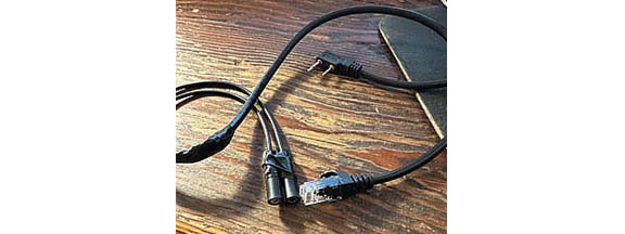
12) Plug the two audio jacks into their appropriate
3.5mm and 2.5mm plugs on the K-1 end of the USB
cable and use electrical tape to hold them together
for the proper spacing.
|
Click above to Enlarge |

Click above to Enlarge |
Parts Reference
- The FTDI Driver was acquired directly from
FTDI Chip
The adapter and FTDI USB cable now work perfectly to
program both my Anytone AT-779UV and my Radioddity
DB20-G in Windows 11 ARM.
|
|
|
|
|